[Author Prev][Author Next][Thread Prev][Thread Next][Author Index][Thread Index]
Re: gEDA-user: Barrie Gilbert
Karel Kulhavy wrote:
Anyone knows what exactly is called Gilbert cell?
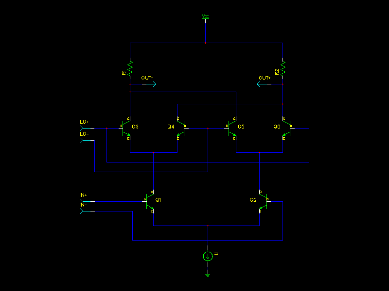
Usually when someone says "Gilbert cell" they are refering to the double
balanced mixer which I've attached as "double_balanced.png".  It is
basically just a differential amplifier (Q1, Q2, R1, R2, and current
source I1).  The four transistors in between the input diff pair are
driven hard enough to fully switch them on or off.  The switching core
(Q3, Q4, Q5, Q6) either deliver the current from Q1/Q2 straight through
to the load resistors or they cross them.  This effectively does a
multiplication by +/- 1.
> How many transistors does it
actually have?
There are many variations, but the 6 transistor circuit I drew is a
somewhat minimimal version.  You might use another for a current source,
you might cascode the thing, etc.
And does it have a tanh nonlinear response from one differential
input or is there some kind of split current mirror used to factor this
nonlinearity out and get a perfect linear analog multiplier?
In the circuit above, the LO port is meant to be driven hard and the IN
port has the same linearity issues/limitations as your usual
differential amplifier.
If you are looking for a circuit where the output is Vout = V1 * V2 /
Vref, i.e. a true analog multiplier, then you need more than the circuit
above.  I'll come back to this.
Is it possible to make a well working Gilbert cell with ordinary non-matched
transistors?
Depends what you mean by well working.  In terms of the double balanced
mixer above, matching helps but isn't super critical.  Imperfect
matching will give some even order distortion and also some imperfect LO
and IN to OUT isolation.  In other words, you'll see some of the LO
signal and some of the IN signal at the output as well as the desired
mixing product.
And btw do you know what translinear mean?
Search for "translinear principle".
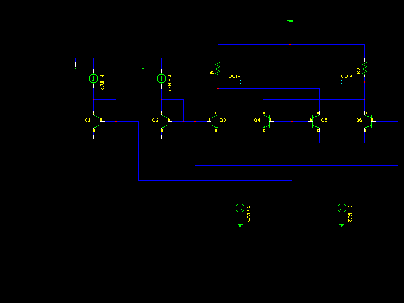
In the 2nd schematic, "multiplier.png", write out KVL:
Vbe2 - Vbe3 + Vbe4 - Vbe1 = 0
Vbe2 - Vbe6 + Vbe5 - Vbe1 = 0
Using Vbe = Vt * log( Ic / Is ) for a biplar transistor, you end up with
Vt*log(Ic2/Is) - Vt*log(Ic3/Is) + Vt*log(Ic4/Is) - Vt*log(Ic1/Is) = 0
Vt*log(Ic2/Is) - Vt*log(Ic6/Is) + Vt*log(Ic5/Is) - Vt*log(Ic1/Is) = 0
The Vt's cancel out, assuming the Is's all match, they cancel out too
and you can use log(x) + log(y) = log(x*y) to get
log(Ic2*Ic4) = log(Ic3*Ic1)
log(Ic2*Ic5) = log(Ic6*Ic1)
and finally, the log()'s can go away to give:
Ic2*Ic4 = Ic3*Ic1
Ic2*Ic5 = Ic6*Ic1
This is really the core of the translinear principle.  Find loops made
of equal numbers of positive and negative junctions and you get a nice
product relationship between the currents.
To finish the analysis of the circuit, we have that:
Ic1 = I1 + IB/2
Ic2 = I1 - IB/2
Ic3 + Ic4 = I0 + IA/2
Ic5 + Ic6 = I0 - IA/2
Iout = differential current into the resistors = Ic3 + Ic5 - (Ic4 + Ic6)
Some amount of algebra later you get Iout = -0.5 * IA * IB / I1.
So maybe I should have chosen a different polarity on my schematic and
arranged to not have the factor of 2 (or maybe I made an algebra
mistake).  But the bottom line is now you have your true 4 quadrant
analog multiplier.  You still of course need a linear transconductor to
turn your two input voltages into differential currents.  You can do
that a variety of ways.  You could just use simple diff amps or you
could use other techniques to improve linearity there.
Now, in my analysis, I ignored base current.  That will cause an error
and if you have mismatches in the current gain of the transistors you'll
get an error for that.  I also assumed identical saturation currents
(Is) for all 6 devices.  Also it was assumed that all devices operate at
the same temperature.  All of these considerations lead you to wanting
to put the devices on the same die.  You should be able to simulate
fairly easily the effects of mismatch on your circuits performance
though.  If you try this with individual devices you probably want to
keep currents and thus self heating low.  I've seen some old circuits
with discrete differential pairs that had heatsinks for two that had a
goal of keeping the two devices at the same temperature.
You can also get into trouble with these translinear circuits if you
have parasitic resistances in bad places.  The good news is that bjt's
follow that exponential rule quite well over a fairly large range of
current levels.
Hope this helps.
-Dan
_______________________________________________
geda-user mailing list
geda-user@xxxxxxxxxxxxxx
http://www.seul.org/cgi-bin/mailman/listinfo/geda-user