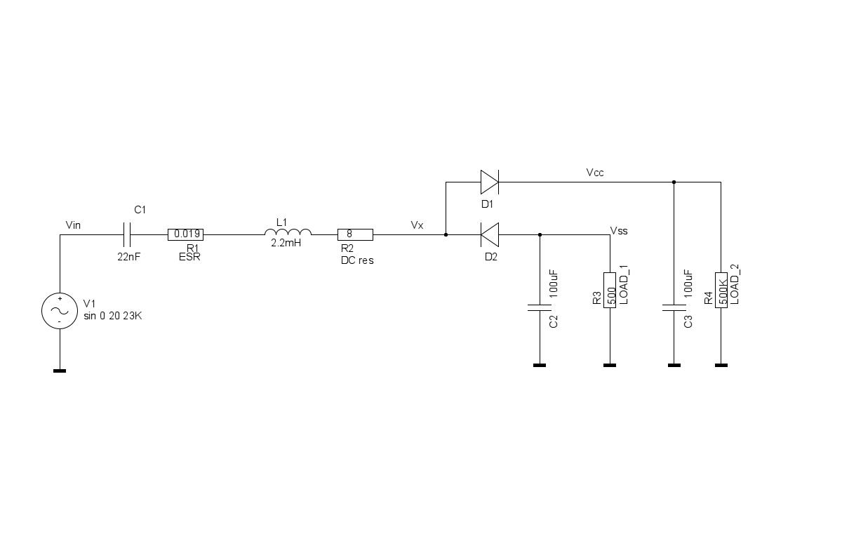
Hello all,

I would appreciate some expert advice.
I have a system which rectifies a sine wave input signal of 20Khz after a LC filter (see Rectifier_sim.jpeg) Everything works fine if LOAD_1 and LOAD_2 are equal. Vx is then (almost) the same as Vin. And Vcc and Vss are equal to the positive or negative part of the sine wave (less the DC losses) (Vss = -Vin_top and Vcc = Vin_top). BUT if LOAD_1 and LOAD_2 are not equal (like in Rectifier_sim.jpeg) it seems that Vx is lifted (DC component added) and Vss moves to the 0V and Vcc is lifted to twice the value I would expect (Vss = 0 and Vcc = Vin_toptop) (see rectifiersmp.eps).
Our real life prototype shows the same behaviour as the simulation.I need this set-up for my system to work and I can not guarantee that the two loads always will be equal.
Vin can be anything between 10Vtt and 90Vtt.I have tried adding a resistor from Vx to ground and that seems to help but increases the current drawn from the source (V1) to a unacceptable level. It should be a low power solution. If I short-circuit C1 everything works fine again (V1 has a low resistance output) but of course will disable the filter, which we don't what.
Is there anyone here who can explain to me how and why this is happening and if available can anyone suggest a solution to me.
I have been wrestling with this problem for a couple of days now, so any help will be very much appreciated.
Many thanks,
Robert
Attachment:
rectifiersmp.eps
Description: image/eps
Attachment:
Rectifier_sim.jpeg
Description: JPEG image
_______________________________________________
geda-user mailing list
geda-user@xxxxxxxxxxxxxx
http://www.seul.org/cgi-bin/mailman/listinfo/geda-user